Flussmesser
More than a century of applications
Besides NMR, Metrolab has historically been especially known for its integrators, primarily in the accelerator world. The many applications and tricks of this powerful technology require much more than a simple web page, but we want to at least provide an overview of some of the basics.
How Fluxmeters, sense coils and voltage integrators work
14 minutes
Advantages
Extremely flexible
Can be very precise
Constraints
Requires developing and calibrating a coil system adapted to the situation
Requires understanding of electromagnetic theory to fully exploit
Requires very careful technique to control electric noise, coil motion, thermal expansion, thermocouple effects, etc.
Fluxmeters: more than a century of applications
Moving a coil in a magnetic field induces a voltage proportional to the change in flux seen by the coil. Similarly, a varying field induces a voltage on a stationary coil. These principles have been understood and exploited since the 19th century to precisely measure, for example, the earth’s magnetic field. Fluxmeters also continue to play an important role in the measurement of the hysteresis of magnetic materials and in magnet design, for example to determine the losses in a magnetic circuit.
A coil: the most flexible of all magnetic probes
The use of coils is limited only by the imagination. How do you measure the flux density inside a solid piece of iron? Certainly not with a Hall sensor – try a search coil tightly wrapped around the block. How about the field induced by an MRI gradient coil, with frequencies in the MHz range? Again, you’ll have better luck with a single turn of wire than with the most elaborate Hall instrument.
Standard coil configurations
Although coils come in all shapes and sizes, a few standard configurations cover many applications:
- Moving coils are moved from the measurement location to another location, usually an area of zero field. The voltage integral is proportional to the total flux change, regardless of the exact path followed by the coil.
- Moving wires for mapping very narrow-gap magnets, by measuring the voltage changes in a wire swept through the gap.
- Flip-coils rotate in place to measure the field at a particular location. Since the coil returns exactly to where it started, the flux change is known to be zero, allowing for very precise drift correction.
- Static coils are used to measure varying fields. Periodic sampling of the voltage integral provides the exact form of the field ramp.
- Rotating coils and moving wires are used for field mapping.
Bucking coils
Imagine two coils, side by side, identical except one is wound clockwise and the other counter-clockwise, wired in series. A global field change, seen by both coils, will generate a negative voltage in one coil and positive in the other; the one coil will cancel out (“buck out”) the other and yield a zero total response. If, however, the field changes more in one coil than the other, a non-zero voltage is generated. In fact, this arrangement provides a direct measure of the field gradient. Since the potentially large common term that could swamp our integrator is cancelled out, bucking coils allow field gradients to be measured with great precision.
Integrators
Since the voltage induced on the coil is proportional to the flux change, we need to integrate the voltage to obtain the change in flux:

There are two commonly used approaches to building an integrator; each has its limitations:
- A standard analogue integrator circuit, using a high-gain amplifier with a capacitive feedback. The low-end bandwidth is limited by the size of the capacitor, and there are numerous analogue noise sources, such as leakage currents and temperature dependence. In addition, we usually want a digital result, so we have to digitize the output anyway.
- Digitize the voltage at periodic intervals and perform a numerical integration. This method has to limit the high-end bandwidth to satisfy the Nyquist criterion, it depends critically upon the linearity of the ADC, and can suffer from quantification noise.
Kalibrierung
The magnetic flux is defined as the integral of the field strength B over the area of the coil A:

If the field strength is constant over the area of the coil, the integrated voltage gives the change in field strength B:

where A is the effective area of the coil and theta is the angle between the coil’s axis and the field. To precisely measure magnetic field strengths with a fluxmeter, it is therefore essential to know the effective area of the coil with a great deal of precision. This is usually achieved by calibrating the coil in a known magnetic field. For measurements with 100 ppm or better precision, this requires an NMR-controlled or -stabilized reference magnet.
More technologies
Products
Related products
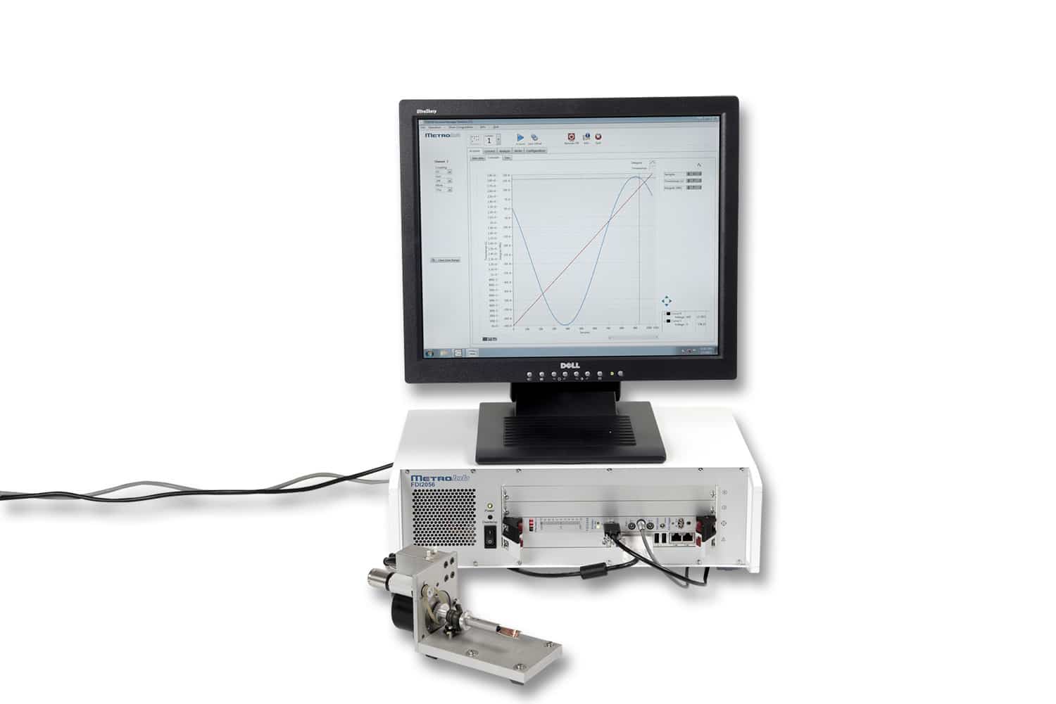
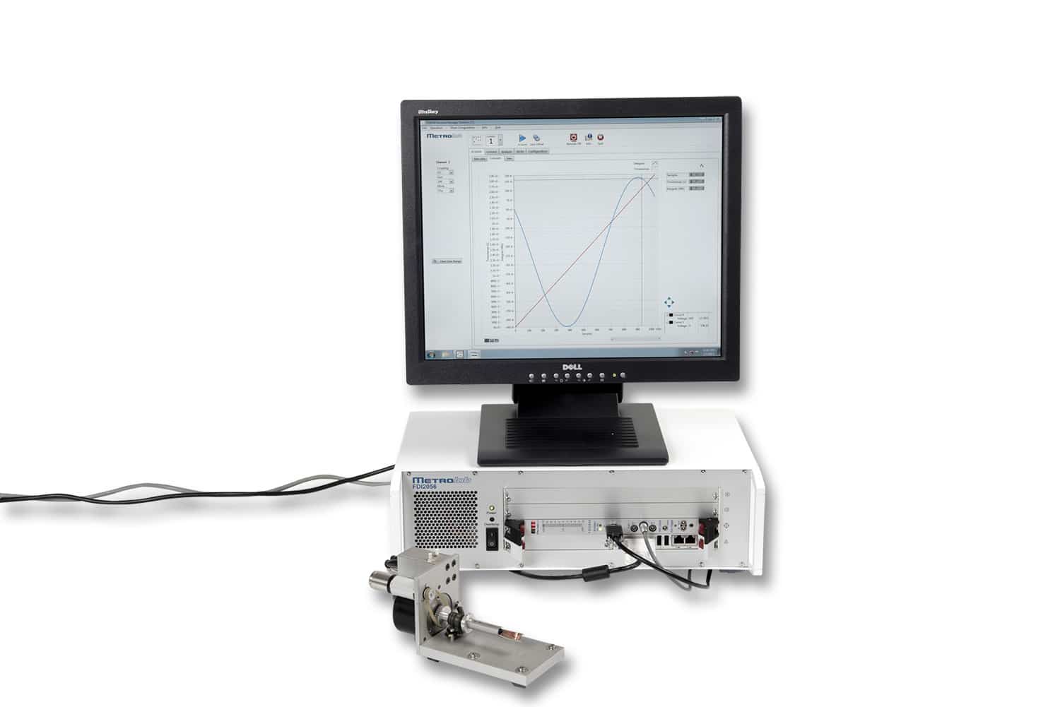
FDI2056 Fast Digital Integrator
The first off-the shelf instrument to quantify magnetic field transients
Applications
Related applications
Science
Mapping accelerator magnets
Want to know more ?
Contact us for more information !
